Mitsubishi Electric PUHZ-SW50VHA Service Manual
Browse online or download Service Manual for Split-system air conditioners Mitsubishi Electric PUHZ-SW50VHA. Mitsubishi Electric PUHZ-SW50VHA Service manual User Manual
- Page / 60
- Table of contents
- TROUBLESHOOTING
- BOOKMARKS
- SERVICE MANUAL 1
- SAFETY PRECAUTION 2
- REFERENCE MANUAL 2
- [1] Cautions for service 3
- [3] Service tools 4
- Dimension A 5
- Dimension B 5
- 3 FEATURES 6
- 4 SPECIFICATIONS 6
- MICROPHONE 8
- 6 OUTLINES AND DIMENSIONS 9
- 7 WIRING DIAGRAM 10
- 8 WIRING SPECIFICATIONS 11
- 9 REFRIGERANT SYSTEM DIAGRAM 12
- 10 TROUBLESHOOTING 14
- 63HS) exceeds 70: 17
- •V•W phase) to 20
- SW40/50 63 61 60 58 56 53 50 23
- 10-4. TROUBLESHOOTING 24
- • Before repair 31
- Motor for compressor 34
- Linear expansion valve 34
- (LEV-A/ LEV-B) 34
- For SW40-50 34
- DC DC250~330V 35
- CC DC15V 35
- <Composition> 38
- (Voltage between pins 39
- (when stopped), DC 1– 39
- (when operated) 39
- → Transmitting signal 41
- Power consumption 43
- (SW1 on) 43
- Detailed 44
- The ones digit : Relay output 46
- SW2 setting 47
- Display detail 47
- Explanation for display 47
- Capacity Code 49
- SW50V 10 49
- Explanation for display Unit 52
- •The ones digit 53
- 11 DISASSEMBLY PROCEDURE 55
- OPERATING PROCEDURE PHOTOS 56
- Made in Japan 60
Summary of Contents
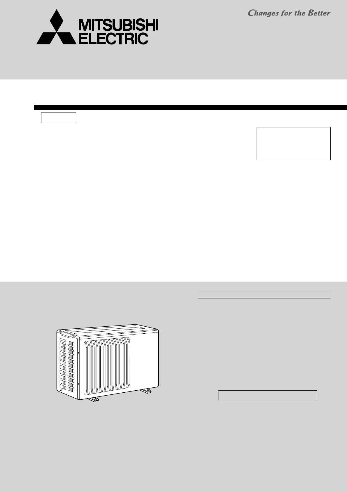
SERVICE MANUALNo.OCH525SPLIT-TYPE, HEAT PUMP AIR CONDITIONERSR410AOctober 2012Outdoor unit[Model name]PUHZ-SW40VHAPUHZ-SW50VHA[Service Ref.]PUHZ-SW40V
107 WIRING DIAGRAMSYMBOL NAME SYMBOL NAME SYMBOL NAMETB1MCMF121S463H63HSTH3TH4TH6TH7TH8TH34LEV-A, LEV-BACLCY1, CY2Terminal Block <Power Supply, Ind
118 WIRING SPECIFICATIONS8-1. FIELD ELECTRICAL WIRING (power wiring specifications)Notes: 1. Wiring size must comply with the applicable local and nat
129 REFRIGERANT SYSTEM DIAGRAMPUHZ-SW40VHA PUHZ-SW40VHA-BSPUHZ-SW50VHA PUHZ-SW50VHA-BSUnit : mm (inch)Refrigerant flow in coolingRefrigerant flow in h
139-1. Refrigerant collecting (pump down)Perform the following procedures to collect the refrigerant when moving the indoor unit or the outdoor unit.1
1410 TROUBLESHOOTING10-1. TROUBLESHOOTING <Error code display by self-diagnosis and actions to be taken for service (summary)>Present and past e
1510-3. SELF-DIAGNOSIS ACTION TABLE<Abnormalities detected when the power is put on>(Note 1) Refer to indoor unit section for code P and code E.
16Error CodeAbnormal points and detection method Judgment and actionEbMiswiring of indoor/outdoor unit connecting wire (converse wiring or disconnecti
17Error CodeAbnormal points and detection method Judgment and actionU1High pressure (High-pressure switch 63H operated)Abnormal if high-pressure switc
18Error CodeAbnormal points and detection method CaseJudgment and actionU5Temperature of heatsinkAbnormal if heatsink thermistor (TH8) detects tempera
Error CodeAbnormal point and detection methodCaseJudgment and action19U9Detailed codesTo find out the details about U9 error, turn ON SW2-1, 2-2, 2-3
22-1. ALWAYS OBSERVE FOR SAFETYBefore obtaining access to terminal, all supply circuits must be disconnected.2SAFETY PRECAUTION2-2. CAUTIONS RELATED T
Error CodeAbnormal points and detection method CaseJudgment and action20UPCompressor overcurrent interruptionAbnormal if overcurrent DC bus or compres
Error CodeAbnormal points and detection method Judgment and actionCase21E0orE4Remote controller transmission error (E0)/signal receiving error (E4)1 A
Error CodeAbnormal points and detection method Judgment and actionCase22E9Indoor/outdoor unit communication error (Transmitting error) (Outdoor unit)1
23Error CodeAbnormal points and detection method Judgment and actionCaseFreezing/overheating protection is oper-ating Overheating protection <Hea
24A fl owing water sound or occasional hissing sound is heard. These sounds can be heard when refrigerant and/or water is (are) fl owing in the indoor
2510-5. TROUBLESHOOTING BY INFERIOR PHENOMENA PhenomenaFactor Countermeasure1. Remote controller display does not work.2. “PLEASE WAIT” display is rem
26PhenomenaFactorCountermeasure7. Remote controller display works normally and the unit performs heating operation, however, the capacity cannot be fu
27How long is “PLEASE WAIT” kept being displayed on the remote controller?6 minutes or more2 minutes or less2 to 6 minutesNONOYESYESAre any error code
28AC 198V to AC 264V?AC 198V to AC 264V?AC 198V to AC 264V?DC 12V to DC 16V?DC 12V to DC 16V?NOYESNOYESNOYESYESNOYESNOCheck the voltage between S1 an
29AC 198V to AC 264V?Are there looseness or disconnection of the indoor/outdoor connecting wire?Is anything displayed?DC 17V to DC 28V?Is “E8” display
3[1] Cautions for service(1) Perform service after recovering the refrigerant left in unit completely.(2) Do not release refrigerant in the air.(3) Af
30DC 10V to DC 16V?YESNOLightingBlinkingLightingBlinkingCheck the voltage of the terminal block (TB6) of the remote controller.Check the status of the
31The operating display of remote controller does not come on.Phone Calls From Customers How to Respond Note Check if power is supplied to air co
32Phone Calls From Customers How to Respond Note Check the set temperature of remote controller. The outdoor unit cannot be operated if the set
33Air blows out for a while after HEAT operation is stopped.Phone Calls From Customers How to Respond Note This is not a malfunction. The blow
34Phone Calls From Customers How to Respond NoteThis is not a malfunction.This may occur when the operation gets started in the room of high humidity
35Notes · High voltage is applied to the connecter (CNF1, 2) for the fan motor. Pay attention to the service. · Do not pull out the connector (CNF1, 2
3610-8. HOW TO CHECK THE COMPONENTS<Thermistor feature chart>Low temperature thermistors• Thermistor <Liquid> (TH3)• Thermistor <2-phas
37<Output pulse signal and the valve operation>(2) Linear expansion valve operationOpenExtra tightening (about 32 pulse)Pulse number500 pulse
38Main bodyLead wireStopperCoil(3) How to attach and detach the coil of linear expansion valve<Composition>Linear expansion valve is separable i
39<CAUTION> TEST POINT1 is high voltage.10-9. TEST POINT DIAGRAMOutdoor controller circuit boardPUHZ-SW40VHA PUHZ-SW40VHA-BSPUHZ-SW50VHA PUHZ-
42-3. PRECAUTIONS WHEN REUSING EXISTING R22 REFRIGERANT PIPES(1) Flowchart [3] Service tools Use the below service tools as exclusive tools for R410A
40Outdoor noise filter circuit boardPUHZ-SW40VHAPUHZ-SW40VHA-BSPUHZ-SW50VHAPUHZ-SW50VHA-BSLO, NOVoltage of 230V AC is output. (Connect to the ACL)CN52
41Outdoor power circuit boardPUHZ-SW40VHAPUHZ-SW40VHA-BSPUHZ-SW50VHAPUHZ-SW50VHA-BSBrief Check of DIP-IPM and DIP-PFCW Usually, they are in a state of
4210-10. FUNCTION OF SWITCHES, CONNECTORS AND JUMPERS (1) Function of switches *1 Forced defrost should be done as follows.1 Change the DIP SW1-1 on t
43CN31TypesConnectorFunction Effective timingConnectorStartShort OpenAction by open/ short operationEmergency operationWhen power supply ONNormal(2) F
44<Display function of inspection for outdoor unit>The blinking patterns of both LED1 (green) and LED2 (red) indicate the types of abnormality w
45U2U7U1U8UdUFUPUHU6U3U4U5U9P1P2P9P4P5P6P8Indication ErrorErrorcode+1Outdoor controller boardContents Inspection methodLED1 (Green)LED2 (Red)3 blinkin
46<Outdoor unit operation monitor function>[When optional part ‘A-Control Service Tool (PAC-SK52ST)’ is connected to outdoor controller board (C
47SW2 setting1ON23456Display detailExplanation for displayUnitPipe temperature / Liquid(TH3)-40 – 90-40 – 90(When the coil thermistor detects 0°C or b
48SW2 setting1ON23456Display detailExplanation for displayUnitPipe temperature / Liquid (TH3) on erroroccurring-40 – 90– 40~90(When the coil thermisto
49SW2 setting1ON23456Display detailExplanation for displayUnitCapacity setting displayDisplayed as an outdoor capacity code.Codedisplay1ON234561ON2345
5(2) Cautions for refrigerant piping workNew refrigerant R410A is adopted for replacement inverter series. Although the refrigerant piping work for R4
501ON23456°C0 – 255(When the temperature is 100°C or more, hundreds digit, tens digit and ones digit are displayed by turns.)0.1 A0 – 500(When it is 1
SW2 settingDisplay detailExplanation for displayUnitThe black square ( ) indicates a switch position.51Code displayError postponement code history (2)
SW2 settingDisplay detailExplanation for display UnitThe black square ( ) indicates a switch position.521ON23456PulseLEV-A opening pulse on error occu
53SW2 settingDisplay detailExplanation for display Unit:0 – 255(When the temperature is 100°C or more, hundreds digit, tens digit and ones digit are d
54SW2 settingDisplay detailExplanation for displayUnit1ON23456Comp.surface temperature (TH34)-52 – 221-52 – 221(When the comp.shell thermistor detects
5511 DISASSEMBLY PROCEDUREOPERATING PROCEDUREPHOTOSPUHZ-SW40VHA PUHZ-SW40VHA-BS PUHZ-SW50VHA PUHZ-SW50VHA-BS 1. Removing the top panel, service pane
56OPERATING PROCEDURE PHOTOS 4. Removing the thermistor <2-phase pipe> (TH6) and thermistor <Liquid pipe> (TH3) (1) Remove the ser
57OPERATING PROCEDURE PHOTOS 5. Removing the thermistor <Ambient> (TH7) (1) Remove the service panel. (See Photo 2) (2) Remove the top panel.
58OPERATING PROCEDURE PHOTOS 8. Removing the 4-way valve (1) Remove the service panel. (See Photo 2) (2) Remove the top panel. (See Photo 1) (3) R
59OPERATING PROCEDURE PHOTOSPhoto 13Photo 14Compressor (MC)Valve bedSeparatorSeparator fixing screwCompressor fixing nutPower receiverPower receiverOu
63 FEATURESCHARGELESS SYSTEMPRE-CHARGED REFRIGERANT IS SUPPLIED FOR PIPING LENGTH AT SHIPMENTMax. 10m (PUHZ-SW40/SW50)The refrigerant circuit with LEV
HEAD OFFICE : TOKYO BLDG., 2-7-3, MARUNOUCHI, CHIYODA-KU, TOKYO 100-8310, JAPANcCopyright 2012 MITSUBISHI ELECTRIC CORPORATIONDistributed in Oct. 2012
7AkWWkW*/min(CFM)dBdBmm(in.)mm(in.)mm(in.)kg(lbs)kg(lbs)Lmm(in.)mm(in.)Power supply (phase, cycle, voltage) Max. currentExternal finish Refrigerant c
85 DATA5-1. REFILLING REFRIGERANT CHARGE (R410A : kg)U-VU-WW-VService Ref.Compressor modelWindingResistance( )(at 20°C)SNB130FGCM20.640.640.64PUHZ-S
96 OUTLINES AND DIMENSIONSPUHZ-SW40VHA PUHZ-SW40VHA-BSPUHZ-SW50VHA PUHZ-SW50VHA-BSUnit : mm100 mm or more as long as no obstacle is placed on therear
Related products and manuals for Split-system air conditioners Mitsubishi Electric PUHZ-SW50VHA
 (78 pages)
 (12 pages)
 (16 pages)
 (9 pages)
 (22 pages)
© 2020, manymanuals.com. All rights reserved. | 0.959 s |
 Manymanuals.com
 Manymanuals.de
 Manymanuals.fr
 Manymanuals.it
 Manymanuals.pl
 Manymanuals.cz
 Manymanuals.es
 Manymanuals-pt.com
Comments to this Manuals