4
INSTALLATION AND WIRING
●Wiring
The safety related terminals are described in Table.2 and Table.3
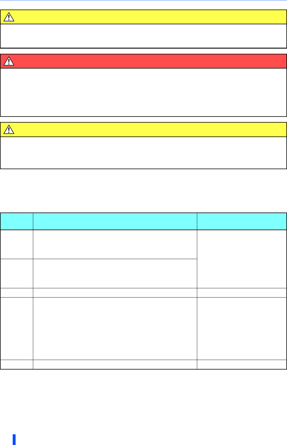
Table.2 The safety related terminals
Specifications for conforming safety standards.
ON: The transistor is conducted. OFF: The transistor is not conducted.
CAUTION
In order to meet safety stop, an approved safety relay unit to ISO13849-1 safety category 3 or better
shall be used in conjunction with FR-A800/F800 as shown in example. In addition, all other
components with in the safety stop loop shall be ‘safety approved’ types.
WARNING
To avoid an electric shock hazard, insert the magnetic contactor (MC) between power source and
drive.
Open the contact of MC and keep away from drive for discharging time (refer to your drive’s User
Manual for information) before performing any work on the drive. And verify that the voltage on the
bus capacitors has discharged before Measuring the DC bus voltage at the P(+) and N(-) terminals or
test points (refer to your drive’s User Manual for locations). The voltage must be zero.
CAUTION
To avoid systematic faults, a test even for faulty demands of the safety function has to be performed
in order to check the correct function of the monitor signal. This test shall be carried out at system
installation, any software changes, parameterization changes, and/or at least once per year. Refer to
‘4. Test and checking failure’.
Terminal
symbol
Description Rating
S1
For input of safety stop channel 1.
S1-SIC is
OFF: In safety stop mode.
ON: Non safety stop mode.
Input resistance: 4.7kΩ
Input current : 4 to 6 mADC
(In case of 24VDC input)
S2
For input of safety stop channel 2.
S2-SIC is
OFF: In safety stop mode.
ON: Non safety stop mode.
SIC Common terminal for S1 terminal and S2 terminal.
SO
As output for failure detection and alarm. SO terminal type is
‘Open collector output’.
SO-SOC is
OFF: Detect failure or alarm.
ON: No failure detected.
Note: This terminal cannot be used to output safety outputs in a
safety system. This terminal can be used for alarm or to
prevent restart only, no other safety function.
Load: 24VDC/0.1A max.
Voltage drop: 3.4V max.
(In case of ‘ON’ state)
SOC Common terminal for SO terminal.
 (65 pages)
 (28 pages)
 Manymanuals.com
 Manymanuals.de
 Manymanuals.fr
 Manymanuals.it
 Manymanuals.pl
 Manymanuals.cz
 Manymanuals.es
 Manymanuals-pt.com
Comments to this Manuals